|
Four State Dummy Load SMD Starter Kit
|
 Click for larger image
|
Assembly Instructions
This is a dummy load kit which is designed to be an inexpensive SMD Starter Kit for those wishing to gain experience
building with SMD’s prior to tackling a more complex kit. It is
hoped that this kit will be a positive SMD building experience and
that it will be a useful addition to your bench. It is an ideal kit for
club and group builds as well.
There are several methods which work well to solder SMD parts.
Solder Paste
Skillet or Griddle
Embossing Gun (Hot Air Flow)
Manually with soldering iron
Accessories to assist in positioning the parts
Magnification Aids (visor magnifiers, strong reading glasses, light magnifiers, etc)
Tweezers
Doofus
Toothpick
Exacto Knife with #11 triangular blade
And probably several others
|

|

Finished SMD Dummy Load
|
Before starting, browse through the pictures below and decide which technique you want to try first. Try them all for a good all around SMD educational experience..
Clean the board with alcohol to remove fingerprints and dust residue, and then
follow the pictures below and use them as a guide to building the kit.
When you finish building this little kit you should feel fairly comfortable with SMD kit construction.
After assembly measure the resistance to determine if all resistors are soldered properly. If the total resistance is less than 51 ohms then all joints are ok.
One bad solder joint will result in a value of about 51.3 ohms.
Here are some links to excellent, and authoritative reference information
Safety Note: If you use Super or Instant Glues to glue the RF Probe pads,
use a gel formulation, wear safety glasses, and use adequate ventilation.
(i.e. DON’T breathe the fumes when tinning Manhattan pads). These glues have irritating chemicals.
List of Materials
R1 – R40 2K 1206 resistors, (marked 2001) ** See Footnote **
R23 4.7M Ľ watt thru hole resistor, yellow violet green
C1 .01 uf (103)
D1 1N5711 Schottky diode, dark blue
1/2” x 4” Slotted Copper Clad Board
3/16”x1.5” Manhattan Pad Strip
Scroll On Down and Have Fun Soldering SMDs!

Parts In The Kit
|
|

Work Within Something to Contain The Parts
|

Resistors Removed From Tape
|
|

Solder Paste From Cash Olsen
|
Paul Alexander (SK), WB9IPA's Skillet Method

Apply Little Dabs of Paste
|
|

Place the Parts with Tweezers
|

Place board in skillet (center is best)
|
|

Preheat for ~2 minutes at 200
|

Crank the heat up
|
|

Wait Until The Solder Paste Melts
|
Then pull the plug and walk away for about a half hour before handling the board.
Cash Olsen, KD5SSJ's Embossing Gun Method
Cash's Hot Air Reflow method uses an embossing gun along with preheating the parts. A cup holder/heater is recommended for preheating, although I use my electric skillet.
The embossing gun is held about 2" above the parts,and the stream of hot air is played over the solder paste until it flows - very easy and effective.
Read a recent post by Cash on the AT_Sprint reflector
When building double sided boards, try combining the skillet and the embossing gun methods. The skillet on one side and the embossing gun on the other - works great!

Embossing Gun From Craft Store
|
|
Hold Approx. 2" Above The Parts.
|
Hand Soldering
Hand soldering isnt difficult on 1206 size components. Please give it a try on this little kit, you'll be glad you did.
It will leave you with a great sense of self satisfaction.

Lightly tin the area before soldering resistors.
|
|

Place and hold the resistor
|

Pick up a small solder droplet on the iron and apply to the joint..
|
|

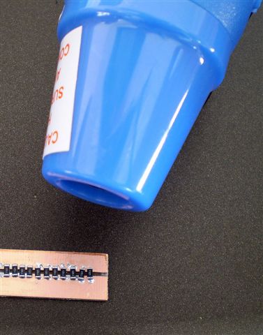
There they are, all in a row - sorta.
|
Add the pads and finish it up.
Complete, RF probe is on the right
|
|

The classic RF Probe circuit.
|
What's a Doofus?
What's a Doofus? It's used to hold down SMD parts while soldering. I first encountered the term on
Jim Larson,
AL7FS's web site.
Here's mine which has been gathering dust since I discovered the skillet and embossing gun.

The classic Doofus Hold Down
|
|

Mine has been relegated to the junque box.
|
** The sharp eyed builder will notice that some pictures show 1.1K resistors, while others show 2K ones.
He will also notice that the quantities changed from 22-1.1K's, to 40-2K's. The first protptype was built with 22-1.1K 1/4 watt resistors. While it worked well,
it became way too hot at 5W without a heat sink, even after only a 2-3 minutes. So the number of resistors was increased to 40. This configuration lives
much better and survived 2 hours at 4W input, After that length of time it was to hot to touch for more than a few seconds, so be careful if you apply power for any length of time.
For personal safety and longevity of the circuit, install the Dummy Load in an aluminum or copper clad enclosure and bolt the board to it using heat sink compound.
Have fun with this little project and drop me a line with any feedback you may have, thank you ...WAŘITP