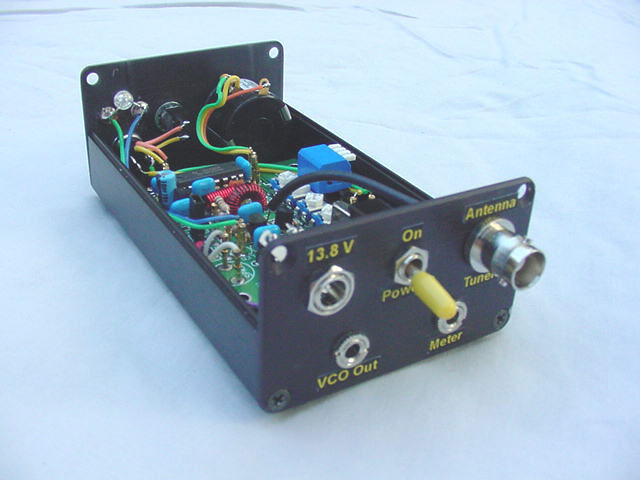
Deluxe KD1JV "Tenna Dipper"
by Chuck Carpenter, W5USJ
My main interest in building
the KD1JV "Tenna Dipper" was to experiment with a VCO circuit to generate
an audible tuning indicator. More about this later.
|
Here's a summary of the changes
made and peripheral parts used for my version of the tenna dipper.
Lever type
DIP switches are used to allow access through a notch in the cover. A sub-miniture
SPST switch for hi/lo selection. A push button switch for program selection
and frequency readout. Power connected through a 5.5 x 2.1 mm coaxial connector.
Power on/off with a SPST miniature switch. Antenna/tuner connection with
a BNC jack. The connection for an external VCO circuit is provided with a 2-circuit audio jack. Voltage for the VCO is taken across the 100 Ohm, R10, resistor in the LED circuit. Other values may be used as needed and still keep the LED visible. |
A spare 2-circuit jack, marked "meter", is also mounted on the back panel. This may be used for an external frequency meter or as an input for some other purpose TBD. |
A revised version of Steve's schematic is available in GIF format showing the connections and changes made for this version of the "Tenna Dipper". |
![]() |
Chuck Carpenter W5USJ
November, 2003