Functional, Easy, and Cheap
All Good Ham Radio Characteristics
By Terry
Fletcher, WAÏITP
When I discovered that I could make my logging program,
ACLog, read the frequency and mode from the big rig, I also saw that I
could cause the rig to jump to the frequency of a DX spot just by clicking
on the spot. Scott, N3FJP, has a very capable, intuitive, and flexible
logging program here. When I mentioned this to a fellow club member, and
darned good op, Dale Stoy, NSÏD he said ôWelcome to the 21rst century.ö
Of course heÆd been controlling his rig like this for a long time. When
super op Steve Miller, NÏSM mentioned that he had his logging program
keying CW on his rig, I felt like I was still in the dark ages, and had
better hurry and catch up.
Why Do It?
Although I really enjoy sending manually, IÆm neither
fast, nor good. But it is very enjoyable, and akin to ôbeing one with
the radioö. Anyone else ever have that feeling? So why should I want to
make my logging program key the rig? Only one reason:
ItÆs fast, efficient, and accurate transmitting when in a contest and
running a frequency (it sometimes happens, even at QRP).
Operating a Special event Station.
Quick, easy, and accurate logging (and MUCH less work than paper)
Easy generation of an ADIF file (emaillable doncha know)
OK, so thatÆs thatÆs a few more than one, but you get the idea.
So I set about working up a interface circuit with these design goals.
1. Simple (or it would be well over my head)
2. Functional (it canÆt mess up characters, I use my paddle for that)
3. Easy to build into a connector shell (I already have a ratÆs nest behind
the computer)
4. Cheap (meaning donÆt buy nothin)
5. Reliable (I donÆt ever want to have to crawl under the desk to unplug
it)
6. Complete isolation between the rig and the computer (no ground loops)
Road Map to Success
Below is a description of the fun that can be had
on a simple project.. It was a great way to spend part of an afternoon,
therapeutic even. You may wish to scroll or jump down to the test
circuit schematics and a picture of the cable connector at the bottom
of the document.
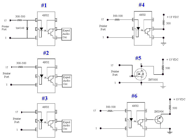
Circuit #1
The first circuit I cobbled together was a 4N32 opto (isolation remember?).
A 270 ohm resistor, 1N914 diode, and an audio oscillator on the output
to monitor. You know the circuit, itÆs on WM2UÆs web site.. A resistor
in series with the optoÆs pin 1 and the diode across the input. ACLog
wants the DB25 pin 1 to be gnd and the signal pin to be 17. It worked
great, called CQ for 30 minutes at 25 wpm, using an audio oscillator,
not on the air. I thought that 30 minutes would demonstrate initial
reliability. It worked well the whole time. But the circuit had too
many parts. Remember I wanted to build the entire interface into the
connector shell. So in the interest of simplicity I removed some parts
and tried again.
Circuit #2
I couldn't figure out why the reverse diode had to be across the input.
The parallel port sigs go from zero (or close) to +5. So why a diode?
Cant imagine any spikes to shunt, the diode in the opto should turn
on and off just fine on signal excursions, no reverse voltages to
contend with, and no need for need any bias. So out it comes! Now
it's down to just the resistor, and the opto.... 30 more minutes calling
CQ and all was still fine.
Circuit #3
Next I wondered if the input resistor was necessary. A little current
measurement shows the opto diode drawing 24 ma on 5 volts with no
series resistor. Hmmmm wonder if the port will stand that? I read
somewhere that early parallel ports were kinda puny but that later
ones were more robust (I like that word). So out comes the resistor
û still works great! Now it was down to 1 part and itÆs looking elegant.
One of the Four State QRP GroupÆs prime movers and OzarkCon organizer
Joe Porter, WÏMQY, sent a note advising that parallel port lines were
rated at only 20ma. Whew! I dodged a bullet that time. I was actually
going to ôfreeze the designö at that point until I heard from him,
thank you Joe!
Circuit #4
Time to get rid of the noisemaker and in the process see if the opto's
output transistor can hack it. So, I plugged the input resistor back
in, rigged up a battery and a resistor, and away the little opto goes
with a 25 ma load.. Half an hour later itÆs still perkin along just
fine, and cool too. Hey Hey, maybe I've got it!! Or maybe not, the
output transistor doesnÆt turn on very hard. It has about .8 volts
from collector to ground. This may be ok, but I didnÆt plug it into
the big rig, since the manual says it wants a half volt or less when
keyed. I thought I had it here for a minute.
Circuit #5, or whatÆs next?
I've become fond of the little 2N7000's so I wondered if I could use
one of those little thingys. Well why not try it. I did and it worked
just fine, all by itself!! It turns on hard (millivolt range) and
ran for 30 minutes solid at a 25ma load and didnÆt even get warm.
At 13 cents apiece, thatÆs a really cheap one part interface.! Of
course any small switching transistor could be used, the ubiquitous
2N2222A for example. Except a current limiting base resistor would
probably be needed û back up to 2 parts..
The single transistor approach doesnÆt meet one of my design goals,
that of complete isolation. I most cases isolation isnÆt a problem
but itÆs seems like a good design practice here. I used an opto in
my homebrew digital interface for the same reason.
Wrap up and build ( or quit
messing around and get it done)
Bottom line: I decided to use the opto and a current limiting input
resistor, keying the line directly with the optoÆs output transistor.
This is circuit #2 with pin #5 connecting to a mono phone plug tip
and pin 4 being rig ground. This circuit will key modern, non tube
rigs, most of which have a positive line going to ground when keyed.
Not only does it key the big rig, it also keys the ATS3 nicely as
well.
In the course of ôspearmintinö, I had tried using a pnp transistor
on the optoÆs output to key the rig, Circuit #6. But I noticed that
the keyed C-E voltage drop was over a volt. So I scrapped that idea
and looked at the optoÆs saturated voltage again. I was surprised
to see it drop to about .1 volt immediately and then rise and stabilize
at the .8 volts I had seen earlier. I donÆt know why that happens,
but it keys the rig nicely, so IÆll stay with it.
The two parts fit inside the connector shell with
loads of room to spare. The resistor needed a little clearance,
so I pulled the cable out a bit before globbing on a wad of hot melt
glue to secure it for strain relief.
AMIDON?
Did I meet the original objectives? I think so, minimal parts count,
it works well, all parts were in the junque box, a snap to stuff inside
the connector shell, and provides complete isolation. Only time will
tell the story on itÆs long term reliability, stay tuned.
Now if I could just learn to type.
72,
Terry, WAÏITP
16 April 2007
*Or, it doesnÆt take much to entertain an olÆ ham..
Click on the schematic for a larger view.

Scroll Back UP
Return to home page
All Good Ham Radio Characteristics
By Terry Fletcher, WAÏITP
When I discovered that I could make my logging program,
ACLog, read the frequency and mode from the big rig, I also saw that I
could cause the rig to jump to the frequency of a DX spot just by clicking
on the spot. Scott, N3FJP, has a very capable, intuitive, and flexible
logging program here. When I mentioned this to a fellow club member, and
darned good op, Dale Stoy, NSÏD he said ôWelcome to the 21rst century.ö
Of course heÆd been controlling his rig like this for a long time. When
super op Steve Miller, NÏSM mentioned that he had his logging program
keying CW on his rig, I felt like I was still in the dark ages, and had
better hurry and catch up.
Although I really enjoy sending manually, IÆm neither
fast, nor good. But it is very enjoyable, and akin to ôbeing one with
the radioö. Anyone else ever have that feeling? So why should I want to
make my logging program key the rig? Only one reason:
ItÆs fast, efficient, and accurate transmitting when in a contest and
running a frequency (it sometimes happens, even at QRP).
Operating a Special event Station.
Quick, easy, and accurate logging (and MUCH less work than paper)
Easy generation of an ADIF file (emaillable doncha know)
OK, so thatÆs thatÆs a few more than one, but you get the idea.
So I set about working up a interface circuit with these design goals.
1. Simple (or it would be well over my head)
2. Functional (it canÆt mess up characters, I use my paddle for that)
3. Easy to build into a connector shell (I already have a ratÆs nest behind
the computer)
4. Cheap (meaning donÆt buy nothin)
5. Reliable (I donÆt ever want to have to crawl under the desk to unplug
it)
6. Complete isolation between the rig and the computer (no ground loops)
Road Map to Success
Below is a description of the fun that can be had
on a simple project.. It was a great way to spend part of an afternoon,
therapeutic even. You may wish to scroll or jump down to the test
circuit schematics and a picture of the cable connector at the bottom
of the document.
Circuit #1
The first circuit I cobbled together was a 4N32 opto (isolation remember?).
A 270 ohm resistor, 1N914 diode, and an audio oscillator on the output
to monitor. You know the circuit, itÆs on WM2UÆs web site.. A resistor
in series with the optoÆs pin 1 and the diode across the input. ACLog
wants the DB25 pin 1 to be gnd and the signal pin to be 17. It worked
great, called CQ for 30 minutes at 25 wpm, using an audio oscillator,
not on the air. I thought that 30 minutes would demonstrate initial
reliability. It worked well the whole time. But the circuit had too
many parts. Remember I wanted to build the entire interface into the
connector shell. So in the interest of simplicity I removed some parts
and tried again.
Circuit #2
I couldn't figure out why the reverse diode had to be across the input.
The parallel port sigs go from zero (or close) to +5. So why a diode?
Cant imagine any spikes to shunt, the diode in the opto should turn
on and off just fine on signal excursions, no reverse voltages to
contend with, and no need for need any bias. So out it comes! Now
it's down to just the resistor, and the opto.... 30 more minutes calling
CQ and all was still fine.
Circuit #3
Next I wondered if the input resistor was necessary. A little current
measurement shows the opto diode drawing 24 ma on 5 volts with no
series resistor. Hmmmm wonder if the port will stand that? I read
somewhere that early parallel ports were kinda puny but that later
ones were more robust (I like that word). So out comes the resistor
û still works great! Now it was down to 1 part and itÆs looking elegant.
One of the Four State QRP GroupÆs prime movers and OzarkCon organizer
Joe Porter, WÏMQY, sent a note advising that parallel port lines were
rated at only 20ma. Whew! I dodged a bullet that time. I was actually
going to ôfreeze the designö at that point until I heard from him,
thank you Joe!
Circuit #4
Time to get rid of the noisemaker and in the process see if the opto's
output transistor can hack it. So, I plugged the input resistor back
in, rigged up a battery and a resistor, and away the little opto goes
with a 25 ma load.. Half an hour later itÆs still perkin along just
fine, and cool too. Hey Hey, maybe I've got it!! Or maybe not, the
output transistor doesnÆt turn on very hard. It has about .8 volts
from collector to ground. This may be ok, but I didnÆt plug it into
the big rig, since the manual says it wants a half volt or less when
keyed. I thought I had it here for a minute.
Circuit #5, or whatÆs next?
I've become fond of the little 2N7000's so I wondered if I could use
one of those little thingys. Well why not try it. I did and it worked
just fine, all by itself!! It turns on hard (millivolt range) and
ran for 30 minutes solid at a 25ma load and didnÆt even get warm.
At 13 cents apiece, thatÆs a really cheap one part interface.! Of
course any small switching transistor could be used, the ubiquitous
2N2222A for example. Except a current limiting base resistor would
probably be needed û back up to 2 parts..
The single transistor approach doesnÆt meet one of my design goals,
that of complete isolation. I most cases isolation isnÆt a problem
but itÆs seems like a good design practice here. I used an opto in
my homebrew digital interface for the same reason.
Wrap up and build ( or quit
messing around and get it done)
Bottom line: I decided to use the opto and a current limiting input
resistor, keying the line directly with the optoÆs output transistor.
This is circuit #2 with pin #5 connecting to a mono phone plug tip
and pin 4 being rig ground. This circuit will key modern, non tube
rigs, most of which have a positive line going to ground when keyed.
Not only does it key the big rig, it also keys the ATS3 nicely as
well.
In the course of ôspearmintinö, I had tried using a pnp transistor
on the optoÆs output to key the rig, Circuit #6. But I noticed that
the keyed C-E voltage drop was over a volt. So I scrapped that idea
and looked at the optoÆs saturated voltage again. I was surprised
to see it drop to about .1 volt immediately and then rise and stabilize
at the .8 volts I had seen earlier. I donÆt know why that happens,
but it keys the rig nicely, so IÆll stay with it.
The two parts fit inside the connector shell with
loads of room to spare. The resistor needed a little clearance,
so I pulled the cable out a bit before globbing on a wad of hot melt
glue to secure it for strain relief.
AMIDON?
Did I meet the original objectives? I think so, minimal parts count,
it works well, all parts were in the junque box, a snap to stuff inside
the connector shell, and provides complete isolation. Only time will
tell the story on itÆs long term reliability, stay tuned.
Now if I could just learn to type.
72,
Terry, WAÏITP
16 April 2007
*Or, it doesnÆt take much to entertain an olÆ ham..
Click on the schematic for a larger view.
Scroll Back UP
Return to home page
